Keywords: Characterizing Bone, Micro-scale testing, viscoelastic bone properties, miniature 4-point bending
EF011
The Challenge
To Determine the Mechanical Properties of Small Bone Specimens.
Background
Bone is a living organ whose structure and function are affected by various factors including mode and frequency of loading, age, and disease1. It is a hierarchical composite material that is made up of a collagen matrix and a mineral reinforcement. This dissimilar structure in the transverse and longitudinal orientations results in the anisotropic mechanical behavior of bone2.
The material properties of bone are being researched on multiple levels (macro, micro, cellular) to gain a better understanding of the material changes and their relevance to applications such as fracture assessment and prediction. This research often involves analyzing forces acting upon various scales of bone material ranging in size from whole bone structures to micro-scale bone sections to individual collagen fibers. To add to the complexity for researchers, each level interacts with the next level, and bone has demonstrated a size dependence on its mechanical properties3.
One specific area of research involves the examination of age-related effects of collagen on the mechanical properties of bone. Creep measurements, commonly used to assess polymeric or other viscoelastic materials, can be informative for studying the effects of age-related changes in the collagenous component of bone.
Meeting the Challenge
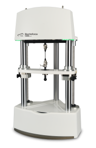
Research performed at Rensselear Polytechnic Institute by Simon Tang and Deepak Vashishth studied the effects of multicyclic loading on human cortical bone4. An Electroforce® 3200 test instrument (Model 3220 with 225N force capacity) with Rensselear researchers’ custom 4-point bend fixture was used to perform the testing to assess the viscoelastic and viscoplastic properties of bone on a micro-scale level5. This study had a threefold purpose: 1) study the creep response of bone to repetitive phsyiologically-relevant loading 2) to perform these types of tests on a small scale; and, 3) to illustrate and identify age-related effects on the mechanical properties of bone.
Materials and Methods
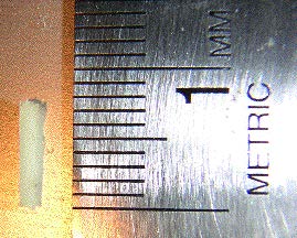
Eighteen longitudinal specimens of cortical bone were collected from the medial side of the femur below the lesser trochanter from 6 human cadavers (3 specimens per donor). The specimens (Figure 2) were then cut into parallelpipeds with dimensions of 0.8 mm~1.2 mm x 0.8 mm~1.2 mm x 6.0 mm using a diamond saw blade. Small markings were made on each specimen outside of the mid-span section to note the anatomically correct loading orientation. This was done to ensure that each microbeam was loaded in a manner similar to its in vivo conditions.
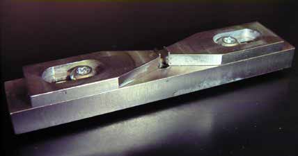
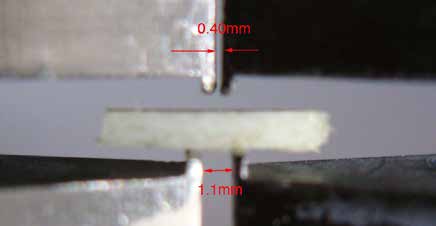
A custom-designed 4-point bend fixture (Figures 3 and 4) was attached to the ElectroForce® 3200 instrument. The bend fixture, which has adjustable upper and lower spans, was configured with an upper span distance of 0.70 mm and a lower span of 2.68 mm. The support points of the top and bottom fixtures are rounded to minimize localized damage to the specimens.
The Electroforce 3200 test system utilizes a proprietary electromagnetic linear actuator design, which provides exceptional force and displacement control over a wide range of frequencies and amplitudes. For these tests, measurements were acquired from a 225N force sensor and a 13 mm displacement sensor using WinTest® control and data acquisition software. This configuration was well-suited for this study due to the instrument’s ability to apply and measure low forces and accommodate customized fixturing. A high-resolution digital camera was used to take photographs of the specimens to independently confirm strain measurements.
The multicyclic testing was performed in force control (Figure 5) and the force, displacement, and geometric parameters of each specimen were used to calculate the stresses and strains.
WinTest’s Block waveform feature was used to implement the test protocol, offering an easy-to-configure sequencing of multiple loading waveforms and control modes. The test method steps were as follows:
1. Ramp to displacement corresponding to 0.5% strain (calculated from each specimen’s unique dimensions)
2. Ramp back to -0.1N preload force
3. Ramp to force corresponding to 35 MPa
4. Hold force for 60 seconds
5. Ramp back to -0.1N preload force
6. Ramp to force corresponding to 65 MPa
7. Hold force for 60 seconds
8. Ramp back to -0.1N preload force
9. Ramp to force corresponding to 70 MPa
10. Hold force for 60 seconds
11. Ramp back to -0.1N preload force
12. Ramp to force corresponding to 75 MPa
13. Hold force for 60 seconds
14. Ramp back to -0.1N preload force
15. Ramp to force corresponding to 80 MPa
16. Hold force for 60 seconds
17. Ramp back to -0.1N preload force
18. Ramp to force corresponding to 85 MPa
19. Hold force for 60 seconds
20. Ramp back to -0.1N preload force
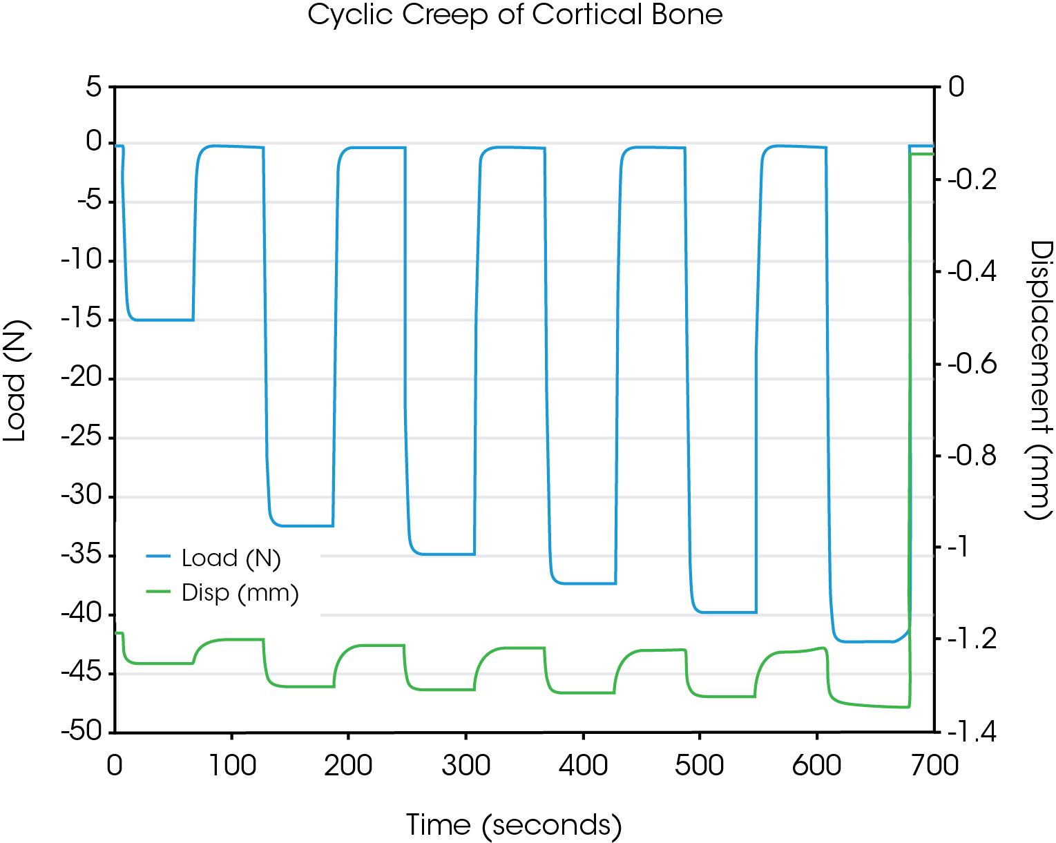
Results and Summary
The bending modulus, which was calculated from the initial bending test, was found to range from 3.7 to 14.7 GPa. These values agreed well with those found in existing literature for similar specimen sizes and loading configurations, indicating that the micromechanical testing used in this study was a valid approach to determining the mechanical properties of smaller bone specimens.
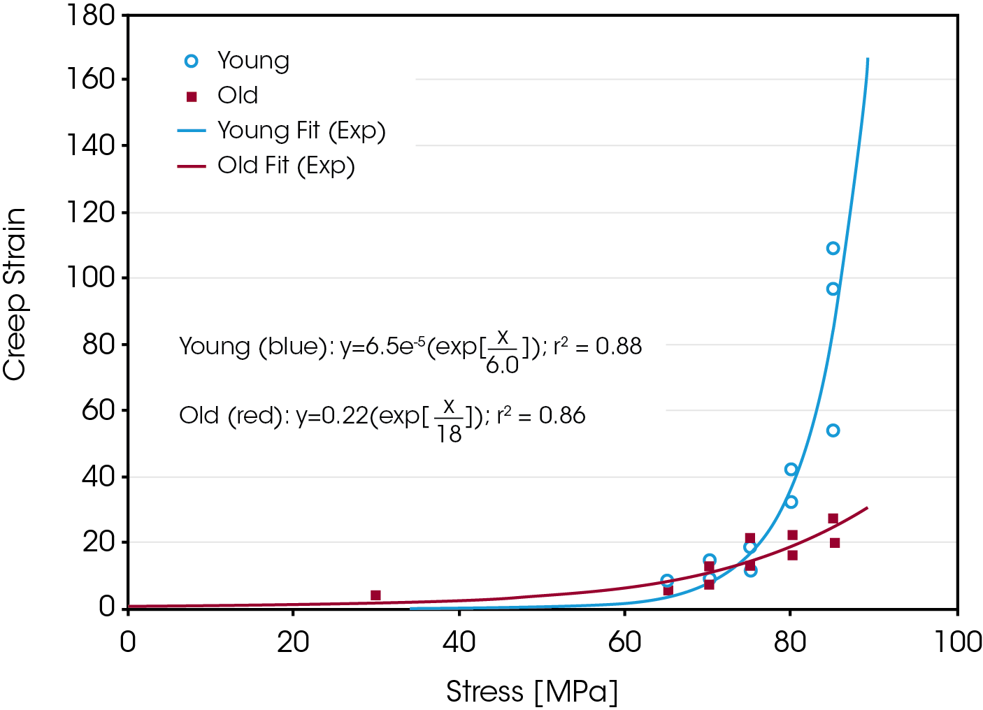
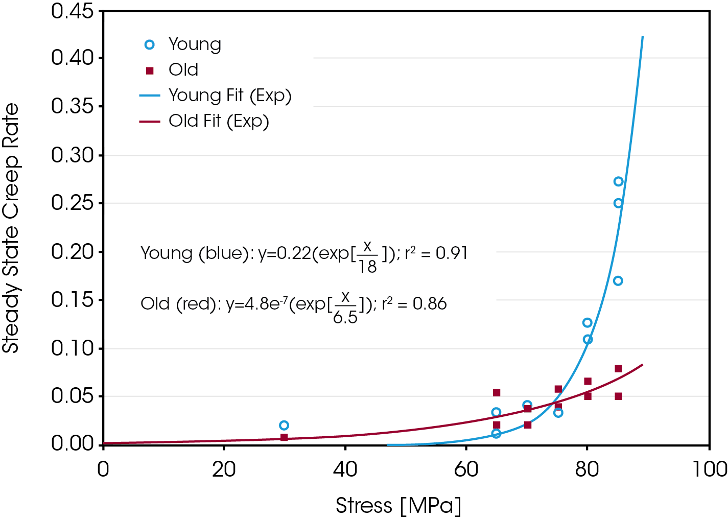
In addition, the study also revealed age-related differences in the material properties of bone. Significant differences were observed in the creep rate and creep strain between younger and older donor bone. It was hypothesized that these results demonstrated a degradation of the collagen network in bone as creep is exhibited by polymers, and the primary polymer in bone is collagen.
References
- Moore KL, Dalley AF, Clinically Oriented Anatomy. 4th Ed., Lippincott Williams & Wilkins, Maryland, 1999.
- Nordin M, Frankel VH, Basic Biomechanics of the Musculoskeletal System. 2nd Ed., Williams & Wilkins, Pennsylvania, 1989.
- Choi K, Kuhn JL, Ciarelli MJ, Goldstein SA., The elastic moduli of human subchondral, trabecular, and cortical bone tissue and the size-dependency of cortical bone modulus. J Biomech. 1990; 23(11):1103-13. Review.
- Tang SY, Vashishth D., Micromechanical multicyclic creep tests show increased fragility of human cortical bone with age. Trans. Of Orthopaedic Res. Soc., 2005.
- Fondrk M, Bahniuk E, Davy DT, Michaels C., Some viscoplastic characteristics of bovine and human cortical bone. J Biomech. 1988; 21(8):623-30.
Acknowledgement
Click here to download the printable version of this application note.

