Keywords: thermal conductivity, xenon flash method, guarded heat flow meter method
TPP032
Background
Thermal conductivity testing can be achieved in both direct and indirect methods. The decision of which method is better suited in each situation is usually determined by multiple factors, namely the sample’s estimated thermal conductivity, sample sizing, and desired temperature profile. In choosing methods, a given user should not have to sacrifice instrument accuracy or repeatability.
Heat Flow Meter Method
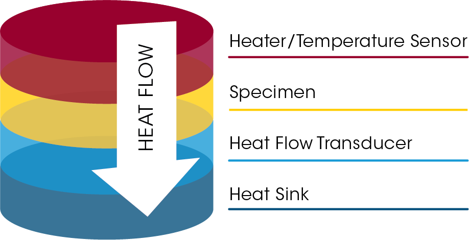
The Guarded Heat Flow Meter Method is a steady state test, in which heat is passed in a uniaxial path through a slab of material and reference calorimeter section to create a thermal gradient in the specimen and calorimeter section.
A sample of material is held under a compressive load between two polished metal surfaces, each controlled at a different temperature. The lower surface is part of a calibrated heat flux transducer. Heat flows from the upper surface through the sample to the lower surface and an axial temperature gradient is established in the stack. By measuring the temperature difference across the sample along with the output from the heat flux transducer, and combined with a known thickness, thermal conductivity of the sample can then be determined. A guard furnace surrounds the test stack to reduce the effect of heat transfer and lateral heat loss across the edges of the sample (which would cause error in measurement). Calibration is required over the thermal resistance range, and the method is limited by the interfacial resistance between the specimen and the instrument, as well as the available specimen thickness.

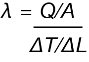
where Q is the amount of heat passing through a cross section of A and causing a temperature difference of ΔT over a thickness of ΔL

Xenon Flash Method
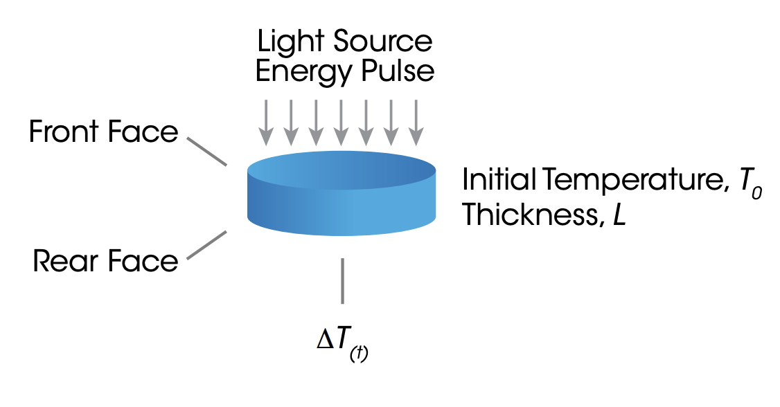
The Flash Method is a test in which a uniform pulse is distributed across the face of a homogeneous sample specimen. The dissipation of the pulse from the center of the sample to the outer edges is recorded and is taken into account with the sample’s thickness to aid in determining its thermal diffusivity.
The determination of thermal conductivity (λ) using the flash method requires the determination of three material properties at the experimental temperatures:
Thermal Diffusivity (α)
- This is determined via direct measurement from the xenon flash experiment
Specific Heat Capacity (Cp)
- Users can use a differential scanning calorimeter (DSC) or flash method to find the Cp
Density (ρ)
- Values are usually found in literature, depending on the sample material; in some cases, density can be mathematically calculated
In compiling the values of these properties, the thermal conductivity is then calculated using the equation below:
λ = α * Cp * ρ

Experimental Parameters
A reference material, Vespel, was tested with both the DTC-300 (Heat Flow Meter Method) and DXF-900 (Xenon Flash Method) instruments. The references were the same for both instruments and were prepared according to the stipulations of the specific instrument.
The DTC-300 requires a disc of 50mm in diameter, and the thickness of the Vespel disc was recorded to be 4.76mm. A thin layer of thermal compound was applied to the sample’s top and bottom faces to assist in promoting its thermal resistance, and making negligible the interfacial resistance between the instrument plates and the sample.
The DXF-900 requires a disc of 25.4mm, and the thickness of the Vespel reference was determined to be 1.34mm. The Vespel reference for the Xenon Flash instrument is pre-coated in gold before the application of a thin layer of graphite spray. These practices aid in allowing the xenon pulse to be held in the sample long enough to produce an accurate thermal diffusivity value.
The thermal conductivity values for Vespel references are well documented, making the verification of the instrument-measured values a matter of comparison. To maximize this comparison, the chosen temperature profile was the largest that both instruments were capable of, though each instrument has its own temperature range.
Results and Conclusion
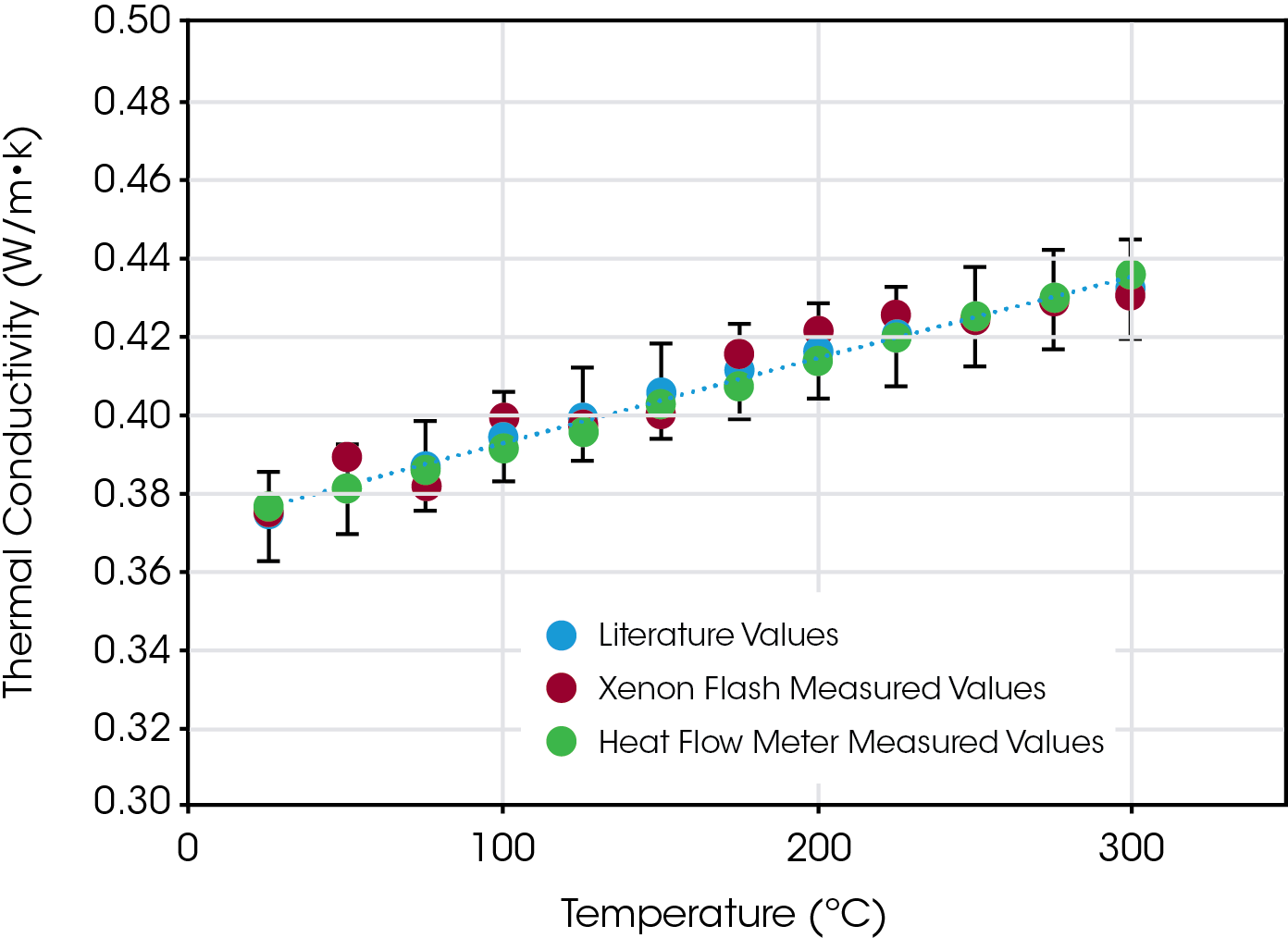
The Literature values of Thermal Conductivity of Vespel follow a general increase of ~0.374 – 0.432 W/m·K from Room Temperature to 300 °C. Both the Xenon Flash and Heat Flow Meter Measured Values follow this same pattern.
The Laser Flash Measured Values have more of a stepwise increase. This is likely due to the overall rounding of the test results to 2 decimal places in the software. The Heat Flow Meter results, however, are produced to 3 decimal places.
A given user can confidently say that the determination of thermal conductivity can be found both directly and indirectly, without sacrificing result accuracy.

Acknowledgement
This application note was written by Justin Wynn, Application Engineer at TA Instruments.
Click here to download the printable version of this application note.

