Palabras clave: batería, cátodo, análisis térmico, SDT, LFP
TA480-ES
Beneficios De La Aplicación
- El SDT Discovery™ de TA Instruments™ permite realizar mediciones simultáneas de DSC y TGA en un solo instrumento
- Las muestras pueden analizarse hasta 1500 °C en diferentes atmósferas controladas para comprender la oxidación y otras interacciones con diversos gases
- Las mediciones del SDT Discovery ofrecen información de la estabilidad térmica, la oxidación, los cambios de fase y las temperaturas de transición de los materiales de las baterías, como el cátodo LFP
Resumen
El fosfato de hierro y litio (LFP) es un material catódico muy utilizado en las baterías de iones de litio. Los investigadores siguen optimizando su conductividad eléctrica mediante revestimientos, morfología modificada o dosificación. El análisis térmico puede ofrecer información sobre la estabilidad, las transiciones de fase y el flujo de calor del LFP para optimizar el procesamiento y comprender los efectos de estas modificaciones. El Discovery SDT de TA Instruments (calorimetría diferencial de barrido (DSC) y análisis termogravimétrico (TGA) simultáneos) mide los cambios de peso y el flujo de calor en un material a lo largo de un intervalo de temperaturas. Las muestras pueden probarse en distintas condiciones ambientales para conocer el contenido del revestimiento, la temperatura de transición de fase y cualquier otra interacción con los gases, incluido si se produce oxidación y en qué momento. El LFP con revestimiento de carbono se probó en aire, nitrógeno y argón, comenzando la oxidación a 325 °C en aire y produciéndose cambios de fase por encima de 900 °C.
Introducción
Desde su desarrollo en la década de 1990, el fosfato de litio e hierro (LFP) se ha convertido en un popular material catódico para las baterías de iones de litio (LIB). Entre sus ventajas, el LFP es rentable, duradero y una de las opciones de material catódico más seguras que existen. Ofrece una gran estabilidad térmica y excelentes propiedades electroquímicas, pero su baja conductividad eléctrica ha dado lugar a continuos esfuerzos para optimizar su desempeño.
Una de las estrategias utilizadas consiste en modificar la superficie del LFP mediante un revestimiento de carbono (C); sin embargo, la fuente de carbono puede influir en el desempeño, así como el grosor del revestimiento. Si el revestimiento es demasiado grueso, puede dificultar la difusión de los iones de litio y disminuir la densidad energética de la batería. En consecuencia, para obtener un alto desempeño es necesario un material compuesto de LFP/C con una fuente y una carga de carbono optimizadas [1]. Otras estrategias incluyen la modificación de la morfología del LFP o la dosificación del material para mejorar la conductividad eléctrica. Comprender la temperatura de transición de fase y las propiedades de flujo térmico puede ayudar a optimizar el proceso, a la vez que se obtienen conocimientos sobre los efectos de cualquier modificación del material. Los LFP pueden oxidarse fácilmente, por lo que hay que tener cuidado en el proceso para evitarlo [2] [3].
Los formuladores y fabricantes necesitan medios eficaces para verificar el contenido de carbono y la integridad de sus revestimientos, comprobar las condiciones de oxidación y comprender el comportamiento de transición de fase. La calorimetría diferencial de barrido (DSC) puede combinarse con el análisis termogravimétrico (TGA) para evaluar los LFP revestidos. El DSC-TGA simultáneo (SDT) mide tanto los cambios de peso como el flujo de calor en un material como una función de la temperatura o el tiempo en una atmósfera controlada de hasta 1500 °C. En este artículo, el SDT se utilizará para identificar la composición del recubrimiento de carbono sobre el LFP a partir del cambio de peso, determinar la temperatura de transición de fase y la entalpía de reacción durante las transiciones de fase a partir de los datos de flujo de calor. Se realizará difracción de rayos X (XRD) para investigar más a fondo la oxidación del LFP y la estructura cristalina.
Experimental
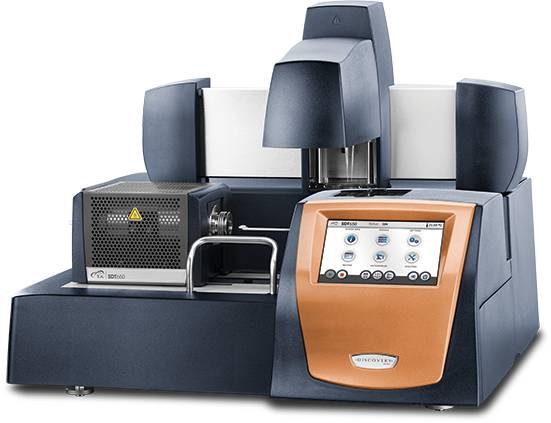
El polvo de LFP recubierto disponible comercialmente fue amablemente proporcionado por NEI Corporation. Para estudiar la degradación del revestimiento y la transición de fase, se compró LFP sin revestir de referencia a Sigma-Aldrich. La pérdida de peso de LFP y el flujo de calor de ambas muestras en nitrógeno se midieron en un SDT 650 de TA Instruments (Figura 1). Las muestras de NEI revestidas se analizaron bajo gases de purga adicionales de argón y aire para observar el efecto de la atmósfera. Las muestras se sometieron a una rampa de 20 °C/min desde la temperatura ambiente hasta 1200 °C. Para la mayoría de las pruebas se utilizaron bandejas de alúmina y zafiro, pero se sugirió utilizar bandejas de zafiro por encima de la temperatura de fusión para evitar que se pegaran a la viga del SDT.
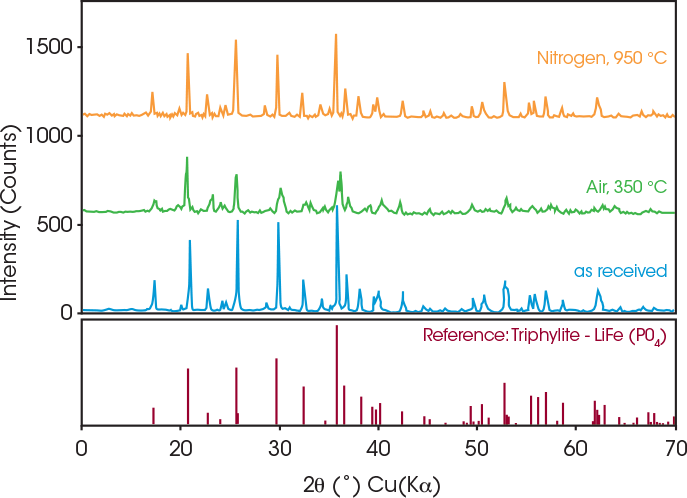
Además del SDT, se llevaron a cabo experimentos de XRD para investigar los cambios en la estructura cristalina del LFP revestido tras ser expuesto a altas temperaturas. Se realizaron dos experimentos de recocido bajo diferentes condiciones atmosféricas. En el primero, los polvos de LFP se recocieron en un horno mufla calentándolos a 350 °C a una velocidad de 5 °C/min, manteniéndolos a continuación a esa temperatura durante dos horas antes de enfriarlos a una velocidad de 10 °C/min. El segundo grupo de polvos se recoció en una atmósfera de nitrógeno colocando los polvos en un horno tubular, prellenado con gas nitrógeno durante 30 minutos a una velocidad de 200 ml/min para eliminar el aire residual. A continuación, los polvos se calentaron a 950 °C a una velocidad de 5 °C/min, se mantuvieron a esa temperatura durante dos horas y se enfriaron a temperatura ambiente a una velocidad de 10 °C/min. Los polvos prístinos y los correspondientes polvos recocidos fueron caracterizados por NEI Corporation con un instrumento MiniFlex II XRD de Rigaku Corporation para investigar la estabilidad estructural.
Resultados Y Discusión
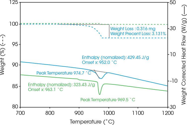
En la Figura 2 se muestra el contenido de recubrimiento de las muestras comerciales de cátodos de LFP en nitrógeno. El cátodo de LFP revestido (azul) mostró una pérdida de peso del 3 % frente a una pérdida de peso no significativa para el LFP no revestido (verde). Como resultado, el material del cátodo de LFP revestido (azul) pierde un 3 % en peso, que es el contenido del revestimiento orgánico y el 97 % restante del material es LFP. Ambas muestras de LFP muestran un pico endotérmico de transición de fusión alrededor de 970 ˚C [4]. El cátodo de LFP recubierto mostró tanto la descomposición del revestimiento como la transición de fase de LFP en el mismo intervalo de temperaturas. Para obtener valores de entalpía más precisos, el flujo de calor endotérmico se traza como flujo de calor corregido por peso para obtener el valor de entalpía ajustado por peso.
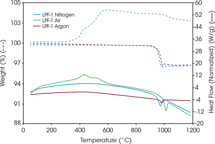
Además del entorno de nitrógeno, las muestras se analizaron en aire y argón para determinar la estabilidad y la interacción con esos gases. La Figura 3 muestra el flujo de calor resultante y la pérdida de peso del LFP revestido en aire, nitrógeno y argón. Bajo nitrógeno y argón, el LFP revestido es estable hasta que la muestra supera los 900 °C, momento en el que el revestimiento comienza a degradarse.
La muestra de LFP revestida en aire experimenta un pico de reacción exotérmica en torno a los 432 °C, y el aumento de peso se sitúa en torno a los 300 °C, lo que probablemente se deba a la oxidación. Como se observa en la Tabla 1, la temperatura pico para el LFP revestido en nitrógeno fue de 975 °C y de 982 °C en argón.
Tabla 1: Temperatura pico endotérmica y pérdida de peso del LFP revestido bajo nitrógeno, aire, y argón
| Gas de purga | Temperatura pico de la endoterma (°C) | Pérdida de peso (%) |
|---|---|---|
| Nitrógeno | 975 | 3.13 |
| Aire | 993 | – |
| Argón | 982 | 3.05 |
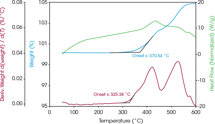
El SDT permite una rápida detección de primera pasada de la estabilidad a la temperatura del LFP. Los resultados pueden utilizarse para seleccionar las condiciones de recocido para el análisis con XRD para evaluar cualquier cambio en la estructura cristalina después de que el LFP haya sido expuesto a altas temperaturas. Las muestras de LFP revestidas se recocieron bajo nitrógeno a 950 °C, donde comienza una transición de fase endotérmica en la Figura 2. Otras muestras de LFP revestidas se recocieron a 350 °C bajo aire debido al aumento de peso observado alrededor de esta temperatura en la Figura 3. Este aumento de peso indica que puede producirse oxidación y el análisis SDT puede utilizarse para determinar el grado de oxidación. La señal de peso de la primera derivada representada en la Figura 4 muestra la tasa de aumento de peso y un inicio a 325 °C.
La oxidación se confirmó mediante el correspondiente experimento de XRD, como se muestra en la Figura 5. La fase de impureza se forma cuando los polvos se recuecen en aire, lo que indica que se produce una reacción de oxidación entre los polvos revestidos de LFP y el oxígeno en el aire a 350 °C. No se observó ninguna fase de impurezas cuando los polvos de LFP revestidos se recocieron en atmósfera de nitrógeno. Sin embargo, los picos parecen ensancharse, lo que podría deberse a una “distorsión” de la red inducida térmicamente. [5] [6] Esto podría estar relacionado con pequeños cambios en la estructura cristalina debidos al recocido a 950 °C, temperatura a la que comienza una transición de fase, como muestran los datos del SDT de la Figura 2.
Conclusiones
El SDT de TA Instruments puede analizar la estabilidad de temperatura y las transiciones de fase de los materiales activos en cátodos de LIB. Las temperaturas de reacción, la energía liberada, los cambios de peso e interacciones con aire, nitrógeno y argón. La muestra de LFP estudiada en este trabajo presentaba un recubrimiento de 3 % en peso de material orgánico. Era estable en nitrógeno y argón hasta 900 °C, mientras que las muestras de LFP en aire se oxidaron a 370 °C y luego mostraron una temperatura de transición de fase más alta. Esta oxidación se confirmó posteriormente mediante análisis de XRD. Además de proporcionar información sobre la estabilidad de los materiales catódicos, los resultados del SDT también pueden utilizarse para determinar la estructura cristalina del LFP a temperaturas de interés, como las temperaturas de oxidación o de transición de fase.
Referencias
- E. Avci, «Enhanced cathode performance of nano-sized lithium iron phosphatecomposite using polytetrafluoroethylene as carbon precursor,» Journal of Power Sources, vol. 270, pp. 142-150, 2014.
- Z. Ahsan, B. Ding, Z. Cai, W. Yang, Y. Ma and M. S. Javed, «Recent progress in capacity enhancement of LiFePO4 cathode for Li-ion batteries,» Journal of Electrochemical Energy Conversion and Storage, vol. 18, no. 1, 2021.
- K. Kretschmer, «Phosphate-based cathode materials for rechargeable batteries,» 2018.
- M. Gauthier, C. Michot, N. Ravet, M. Duchesneau, J. Dufour, G. Liang, J. Wontcheu, L. Gauthier and D. D. MacNeil, «Melt Casting LiFePO4 : I. Synthesis and Characterization,» Journal of The Electrochemical Society, vol. 157, no. 4, pp. A453-A462, 2010.
- T. Ungár, «Microstructural parameters from X-ray diffraction peak broadening,» Scripta Materialia, vol. 51, no. 8, pp. 777-781, 2004.
Reconocimiento
Este trabajo se llevó a cabo en colaboración con NEI Corporation (Somerset, Nueva Jersey). La redacción estuvo a cargo de la Dra. Jennifer Vail, el Dr. Andrew Janisse, especialistas de aplicaciones de TA Instruments y el Dr. Hang Lau, líder científico de desarrollo de nuevos mercados de TA Instruments.
TA Instruments y Discovery son marcas registradas de Waters Technologies Corporation.
Haga clic aquí para descargar la versión imprimible de esta nota de aplicación.

